- 您现在的位置:买卖IC网 > Sheet目录1994 > DS1682S (Maxim Integrated Products)IC TIMEKEEPER ALARM ELAPSE 8SOIC
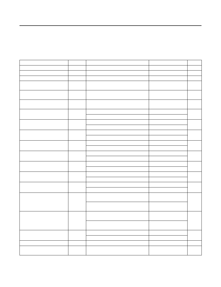
PARAMETER
SYMBOL
CONDITIONS
MIN
TYP
MAX
UNITS
EEPROM Endurance
EE
(Note 2)
50k
writes
EEPROM Write Time
tEW
(Notes 1, 3, 4)
150
300
ms
EEPROM Transfer to RAM
tER
(Notes 1, 5)
1
ms
ALARM Output Active-Low Pulse
Width
tSL
(Note 1)
62.5
ms
ALARM Output Active-High Pulse
Width
tSH
(Note 1)
437.5
ms
ALARM Input Pulled Low
and Released Pulse Width
tSPL
(Note 1)
500
ms
SCL Clock Frequency
fSCL
Fast mode
400
kHz
Standard mode
100
Bus Free Time Between a
STOP and START Condition
tBUF
Fast mode
1.3
s
Standard mode
4.7
Hold Time (Repeated)
START Condition (Note 6)
tHD:STA
Fast mode
0.6
s
Standard mode
4.0
Low Period of SCL
tLOW
Fast mode
1.3
s
Standard mode
4.7
High Period of SCL
tHIGH
Fast mode
0.6
s
Standard mode
4.0
Setup Time for a Repeated
START
tSU:STA
Fast mode
0.6
s
Standard mode
4.0
Data Hold Time (Notes 7, 8)
tHD:DAT
Fast mode
0
s
Standard mode
0
Data Setup Time (Note 9)
tSU:DAT
Fast mode
100
ns
Standard mode
250
Rise Time of SDA and SCL
Signals (Note 10)
tR
Fast mode
20 +
0.1CB
300
ns
Standard mode
20 +
0.1CB
1000
Fall Time of SDA and SCL
Signals (Note 10)
tF
Fast mode
20 +
0.1CB
300
ns
Standard mode
20 +
0.1CB
300
Setup Time for STOP
tSU:STO
Fast mode
0.6
s
Standard mode
4.0
Input Capacitance
CI/O
(Note 1)
10
pF
Capacitive Load for Each
Bus Line
CB
(Note 10)
400
pF
DS1682
Total-Elapsed-Time Recorder
with Alarm
www.maximintegrated.com
Maxim Integrated │ 3
AC Electrical Characteristics
(VCC = 2.5V to 5.5V, TA = -40°C to +85°C, unless otherwise noted.)
发布紧急采购,3分钟左右您将得到回复。
相关PDF资料
DS1683S+T&R
IC REAL TIME EVENT REC 8SOIC
DS1685EN-5/T&R
IC RTC 5V 64BIT Y2K IND 24TSSOP
DS1688S+
IC RTC W/NV RAM CTRL 28-SOIC
DS1689SN+T&R
IC RTC SER NV RAM CTRL IN 28SOIC
DS17285S-3NT
IC RTC 3V 2K NV RAM 24-SOIC
DS1742-100IND
IC RTC RAM Y2K 5V 100NS 24-EDIP
DS1743P-70+
IC RTC RAM Y2K 5V 70NS 34-PCM
DS1744-70IND
IC RTC RAM Y2K 5V 70NS 28-EDIP
相关代理商/技术参数
DS1682S/GG8
制造商:Maxim Integrated Products 功能描述:
DS1682S/T&R
制造商:Maxim Integrated Products 功能描述:REAL TIME CLOCK SERL 10BYTE 8SOIC - Tape and Reel 制造商:Maxim Integrated Products 功能描述:IC TIMEKEEPER ALARM ELAPSE 8SOIC
DS1682S/T&R
功能描述:实时时钟 Total-Elapsed-Time Recorder w/Alarm RoHS:否 制造商:Microchip Technology 功能:Clock, Calendar. Alarm RTC 总线接口:I2C 日期格式:DW:DM:M:Y 时间格式:HH:MM:SS RTC 存储容量:64 B 电源电压-最大:5.5 V 电源电压-最小:1.8 V 最大工作温度:+ 85 C 最小工作温度: 安装风格:Through Hole 封装 / 箱体:PDIP-8 封装:Tube
DS1682S/TR
制造商:Maxim Integrated Products 功能描述:
DS1682S+
功能描述:实时时钟 Total-Elapsed-Time Recorder w/Alarm RoHS:否 制造商:Microchip Technology 功能:Clock, Calendar. Alarm RTC 总线接口:I2C 日期格式:DW:DM:M:Y 时间格式:HH:MM:SS RTC 存储容量:64 B 电源电压-最大:5.5 V 电源电压-最小:1.8 V 最大工作温度:+ 85 C 最小工作温度: 安装风格:Through Hole 封装 / 箱体:PDIP-8 封装:Tube
DS1682S+T&R
制造商:Maxim Integrated Products 功能描述:REAL TIME CLOCK SERL 10BYTE 8SOIC - Tape and Reel 制造商:Maxim Integrated Products 功能描述:IC TIMEKEEPER ALARM ELAPSE 8SOIC
DS1682S+T&R
功能描述:实时时钟 Total-Elapsed-Time Recorder w/Alarm RoHS:否 制造商:Microchip Technology 功能:Clock, Calendar. Alarm RTC 总线接口:I2C 日期格式:DW:DM:M:Y 时间格式:HH:MM:SS RTC 存储容量:64 B 电源电压-最大:5.5 V 电源电压-最小:1.8 V 最大工作温度:+ 85 C 最小工作温度: 安装风格:Through Hole 封装 / 箱体:PDIP-8 封装:Tube
DS1682X
制造商:DALLAS 制造商全称:Dallas Semiconductor 功能描述:Total Elapsed Time Recorder with Alarm